[ Sep
15-17
] Save the date for Autodesk 2026
[ Sep
15-17
] Save the date for Autodesk 2026
 Email:
inquiry@srinsoft.engineering
Email:
inquiry@srinsoft.engineering Phone:
+1 (614) 552-3888
Phone:
+1 (614) 552-3888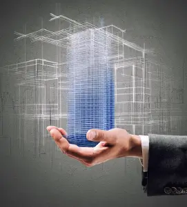

 Add Us On Google
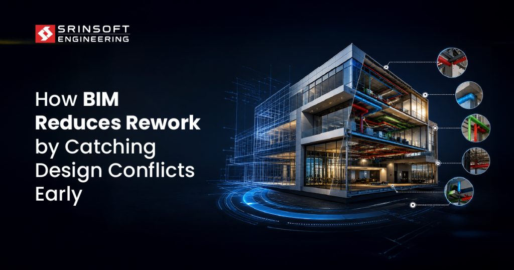
Most design problems that appear on a construction site were already there in the design. They just weren’t visible. The drawings looked finished, the set was issued, and the conflict stayed hidden until the building started going up. By then it costs real money to fix, because now it involves materials that are already ordered, work that has to be undone, and time the schedule doesn’t have.
This is where BIM changes things for architects. Instead of problems surfacing on site, they surface in the model, while the fix is still cheap. When every discipline works in one shared 3D model, conflicts become visible on screen long before anyone breaks ground. That single shift, catching issues in the model instead of the field, is what protects the budget, the program, and the design itself.
Here is how it works.
Why design issues slip through in traditional 2D/CAD workflows
The problem with 2D coordination isn’t a lack of effort. It’s the method.
In a traditional CAD workflow, the architectural, structural, and MEP drawings are produced separately. Each discipline works on its own sheets, and then someone has to check those sets against each other manually. That cross-checking is where things break down, because no one can reliably hold every dimension, level, and system across dozens of sheets and catch every conflict. Some always get missed.
Two other weaknesses make it worse. First, when a change is made in one place, it doesn’t automatically update everywhere else it appears. Each affected drawing has to be found and corrected manually, and the one that gets missed is usually the one that causes trouble on site.
Second, a flat 2D drawing can’t reveal spatial conflicts between building systems. You can’t see that a duct passes through a beam on a drawing. That kind of conflict usually stays hidden until the mock-up or the actual installation, which is the worst possible time to discover it.
Where BIM catches design issues
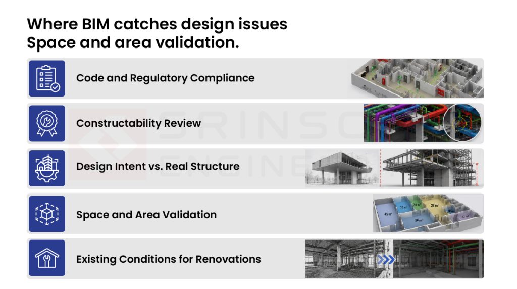
Once every discipline is brought together into one federated model, that shared model can be checked in ways a set of separate drawings never could. Several different kinds of issues get caught, and it’s worth being clear that these are different checks, not one.
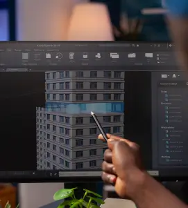
Spatial and geometric clashes. This is clash detection in the strict sense: the model is checked for every place where two physical elements run into each other or leave no room for each other, a duct crossing a structural beam, recessed lighting fighting a beam in the ceiling, pipework with nowhere to run above the ceiling grid. These geometric conflicts are the most common problems on any project. Each one caught early is an RFI and a rework event that never happens on site.
Code and regulatory compliance. This is a separate check, and an important distinction. Because a model carries information, not just lines, it can be tested against rules through what’s called rule-based model checking. This is not the same as clash detection. It confirms things a geometric check can’t, egress widths, fire-rated separations, and accessibility clearances at doors and turning spaces. Checking these against the model during design is far safer than discovering a non-compliant corridor after the walls are up.
Constructability. A detail can be geometrically correct and still be hard to build in the order the trades actually work in. A facade connection might be sound on its own but impossible to reach once the surrounding panels are set. Reviewing the model for buildability and using 4D sequencing to check the build order over time, catches the “you can’t physically get to it” problems that a geometry check alone won’t show.
Design intent against real structure. This one isn’t a clash test at all. It’s what the shared model reveals as the design develops. An idea can look effortless in an early massing model and then run into trouble once the structural engineer works it into real sizes and connections. A dramatic span or cantilever is where this usually shows up. Working in one model early means the architect sees what the design actually requires, in beam depth or column size, while there’s still time to adjust it.
Space and area validation. The rooms in a model are real, measurable spaces, so program areas can be checked against the brief as the design develops. If a design move quietly shrinks a required room or pushes the gross area off target, the model shows it straight away rather than in a late audit.
Existing conditions on renovations. On refurbishment work, the biggest risk is that the existing drawings are wrong. Laser scanning the building and converting that scan into a model,
scan-to-BIM, gives an accurate record of what is actually there, so the new design meets the real building on site instead of clashing with an outdated drawing.
At what design stage does this happen?
The catch works best when it’s matched to how developed the model is, and Level of Development (LOD) is the standard way to describe that.
Architectural work is usually developed to LOD 300 through design development and into construction documents. At this level the geometry is accurate, with real sizes and locations you can trust, which is enough for meaningful coordination to begin.
But the level that matters most for coordination is LOD 350. This is the stage that adds the connections and interfaces between systems, the clearances and supports, the parts where trades actually collide. It’s a useful distinction to understand, because a check at LOD 300 catches hard geometric intersections but misses clearance problems, no room for a hanger, no space for insulation, no access for maintenance. Those are invisible at 300 and obvious at 350. Serious coordination happens once the model reaches 350 and is combined with the structural and MEP models.
The reason to catch early is simple: the earlier a problem is found, the cheaper it is to fix. A change made in the model costs very little. The same change made on site is expensive, because it now involves materials, labour, and delay.
What this looks like in an architect’s actual workflow
The tools only pay off if the way the team works changes with them. In practice, that comes down to a few habits.
Share the model with the structural and MEP consultants from early design, not at the construction-documents handoff. Coordination that starts at CD starts too late. Bring the models together for review on a regular rhythm rather than saving a single coordination check for the end, so problems surface while they’re still small and easy to solve. And use the model to walk clients through the design in real time, so intent is confirmed and locked before it turns into an expensive change later.
The payoff: what architects get from catching issues early
The direct return is fewer RFIs, fewer change orders, and much less rework on site, which is real money kept in the project instead of spent unwinding avoidable conflicts. Dodge’s research puts numbers on it: three-quarters of firms report positive ROI on BIM, and 41% of contractors see final construction costs fall by at least 5%, mostly from fewer errors and less rework.
But the payoff architects tend to value most is quieter. The design survives. When the hard problems are solved in the model, the client gets the building they approved rather than a compromised version forced by a conflict found too late. The schedule holds better. And the architect spends construction answering questions instead of defending drawings, which protects both the fee and the relationship.
How Srinsoft supports architects with this
This is the work Srinsoft Engineering does every day. Our teams deliver BIM modeling across the full range from LOD 100 to 500, run multidiscipline coordination and clash detection so conflicts are resolved in the model rather than the field, and provide scan-to-BIM services that give renovation projects an accurate record of existing conditions to design against.
If you want stronger coordination on your next project, talk to our BIM team. We’re happy to look at where the risk sits in your workflow and how to deal with it before it reaches the site.