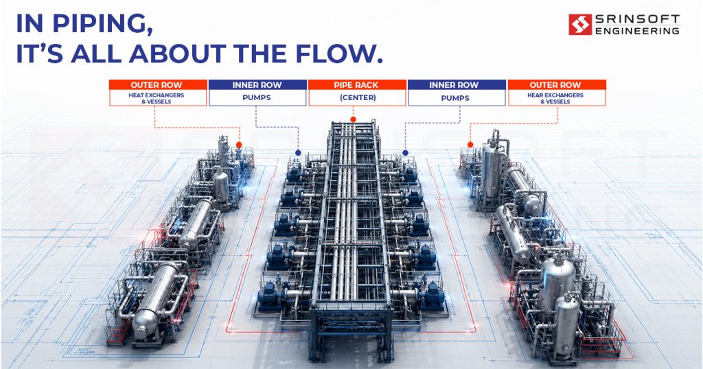
In piping, it’s all about the flow.
Flow inspires layout, and plant layout design starts with understanding the process sequence and operating procedures before anything is placed.
In facility layout planning, equipment follows that sequence: pipe rack centered, splitting the unit into distinct areas; pumps in two rows tight on either side of the rack; heat exchangers and vessels grouped in the outer rows.
This arrangement minimizes pipe runs and keeps maintenance access honest. Spacing is a layout input. When the logic is right from the start, everything downstream costs less to build and less to run.
In this blog article, we cover the most common equipment layout mistakes in piping and plant projects, what they actually cost, and how proper modeling discipline in plant layout design prevents them.
Industrial Design Coordination Issues - Plant Layout Mistakes That Delay Commissioning
Layout mistakes accumulate quietly through early design decisions and surface loudly during detailed engineering, construction, or the first maintenance shutdown.
Equipment Placed Without Pipe Routing Logic
Equipment gets positioned first; structural loads, vendor packages, client preferences. Piping is expected to connect the dots later. It always can. The question is at what cost.
On a gas compression module, compressors were arranged to balance structural load across the skid. Logical from a civil standpoint. From a piping standpoint, the inlet and discharge nozzles faced the wrong direction for the process sequence, forcing the piping team into a layout that added significant pipe length, multiple additional elbows per line, and pressure drops that pushed the design back to process engineering for re-evaluation. The rework happened at 50% detailed design.
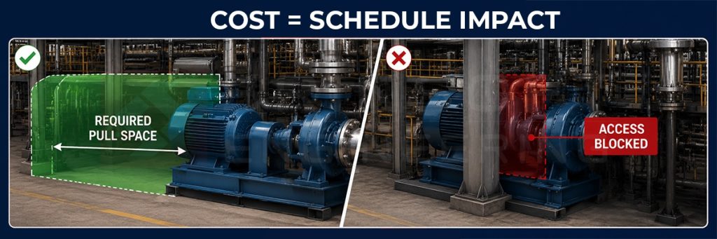
Space Utilization in Industrial Layout – Ignoring Maintenance and Access Space
Coordinates in the model are correct. Clearances are not checked. These are not the same thing.
On a refinery heat exchanger train, equipment was modeled accurately to P&ID and plot plan. Tube bundle pull lengths were never modeled as live envelopes; they were noted in a datasheet and assumed. When the project reached construction, the pull space for two exchangers was obstructed by structural steel that had already been fabricated. The fix required temporary structural modification during the first planned maintenance window. What was budgeted as a routine turnaround activity became a multi-day civil and rigging operation.
No Pipe Corridors or Rack Planning
When rack position and routing corridors aren’t defined early, piping fills available space rather than designated space. So does everything else.
On a greenfield petrochemical unit, the pipe rack location shifted twice during early design. Each time, piping routing was updated informally. Instrument cable trays were routed independently by a separate team working from a different model state. When the full model was issued for interdisciplinary clash detection at 60% completion, it flagged over 200 hard clashes — piping against cable trays, cable trays against str process sequence uctural, piping against access platforms. The resolution took six weeks and pulled four disciplines back into active redesign simultaneously.
Elevation Mistakes
Elevation decisions are actually process decisions with structural and cost consequences attached.
On a condensate recovery system, the receiver drum was set at grade based on plot space availability. The assumption was that pumping would handle transfer. What wasn’t modeled until later was the NPSH requirement for the condensate pumps under actual operating conditions, which required the drum to sit elevated above the pump suction, not at the same level. Two additional pumps and associated pipework were added at detailed design stage. Civil foundations were revised. The correction was entirely avoidable with a 30-minute elevation check at concept layout.
Safety and Clearance Violations
Separation requirements between hazardous equipment are regulatory minimums, and they have to be applied in three dimensions.
On a chemical processing unit, a fired heater was positioned within restricted separation distance of a flammable liquid pump, based on a plot plan review that didn’t account for the actual equipment footprints and radiation zones in 3D. The layout passed internal review. It failed third-party HAZOP at 70% model completion. The area required a full redesign; equipment relocated, pipe rack rerouted, structural supports repositioned. The schedule impact ran to several weeks. The entire situation traces back to a clearance check that should have been run at layout freeze.
Expansion Not Considered
A plant that has no room to grow transfers that constraint to the client permanently.
A utility block was designed tight to the battery limit to maximize plot efficiency. Eighteen months after commissioning, the client requested a capacity expansion that required one additional boiler and associated pipework. There was no room without relocating active infrastructure. Temporary bypasses, live system tie-ins, and partial demolition of recently commissioned work turned a straightforward capacity addition into a project nearly as complex as the original build.

Factory Layout Design – The Hidden Cost of Layout Mistakes
Layout errors that surface at concept stage cost time in a meeting room. The same errors found at detailed design pull civil, structural, piping, and instruments back into active work simultaneously. By that point, foundations may be designed, steelwork may be fabricated, and procurement may be in progress. A single equipment shift moves everything connected to it.

Cost
Rework cost is exponential. A layout correction at 60% detailed design triggers revised drawings across multiple disciplines, potential re-procurement, and contractor variation claims if construction has started. Everything around the equipment got more expensive to move.
Schedule
Every interdisciplinary ripple adds non-recoverable time. One nozzle orientation change updates the piping isometric, which affects the support steel location, which touches the civil foundation drawing. Each discipline has its own review and reissue cycle. Schedule slips in layout-driven rework multiply, because the disciplines aren’t waiting in sequence. They’re all affected at once.
Operability
This is the cost that never appears in a project close-out report. A plant that is difficult to operate, inspect, or maintain transfers that burden to the client for the life of the asset. Maintenance windows run over. Access workarounds become standard practice. Unplanned shutdowns happen more frequently than they should. The layout decision that caused it was made years earlier, under schedule pressure, by a team that never saw the consequence.
3D Factory Layout Design – How Proper Modeling Helps
Layout Logic Before Model Population
For layout, the model needs to carry layout logic from the start — process sequence driving equipment arrangement, rack position defined before piping begins, routing corridors established as constraints. When the model is built around layout rules, the clash count at 60% drops substantially and the clashes that remain are genuine coordination issues.
Maintenance Envelopes and Safety Zones as Modeled Objects
Modeling maintenance envelopes and safety exclusion zones as actual geometry in the 3D environment means they participate in clash detection, show up in model reviews, and create a visible constraint that has to be resolved. What gets modeled gets checked.
Interdisciplinary Coordination Inside the Model
Layout errors compound when disciplines work in separate environments. Piping routes to one model state, structures respond to another, instruments work from a P&ID that hasn’t caught up with either. A single federated model with layout freeze enforced as an actual milestone stops that cascade before it starts.
Early Review at the Right Stage
A targeted layout audit at 30% — equipment arrangement against process sequence, rack position against routing corridors, maintenance access against spacing — catches the mistakes that cost most to fix later. Not a full clash review. One structured review at the right stage eliminates weeks of reactive rework downstream.
Layout is Not a Phase
Good layout thinking is simple: place equipment so that piping runs short, straight, accessible, and safe.
But each discipline has its own priorities and its own timeline. Piping wants short runs. Civil wants stable foundations. Structural wants load balance. Instruments want cable access. When schedule pressure hits, each discipline solves its own problem — and the layout logic that was agreed at the start quietly gets compromised.
The teams that do it well don’t treat layout as a phase. They treat it as a constraint that never switches off.
Work With a Team That Catches It Early
If your projects are carrying layout risk into detailed design, it’s worth a conversation. Srinsoft Engineering works with plant and piping teams to bring layout discipline into the model from day one, before the cost of fixing it compounds.
FAQs
1. Why do we still get clashes even after doing proper layout?
Because what you call “proper layout” is often just equipment placement, not flow-driven layout. If pipe routing logic, access zones, and rack positions weren’t locked early, clashes are inevitable.
2. When should layout actually be frozen in a plant model?
Around 30% design. If layout is still moving at 50–60%, you’re already in rework territory. At that point, piping, structure, and procurement are reacting to changes instead of building forward.
3. Why does a small equipment shift cause so much delay?
Because nothing is isolated. You’re not moving equipment. You’re triggering a multi-discipline chain reaction, which is why late changes explode cost and schedule.
4. Why is pipe length increasing compared to initial estimates?
Because layout wasn’t driven by process flow. Equipment got placed for “fit” or structural convenience, and piping had to compensate. Longer routes, more bends, more cost. That’s a layout failure, not a piping issue.
5. Why did this pass model review but fail during construction or HAZOP?
Because reviews checked geometry, not real constraints. Clearances, safety distances, radiation zones, maintenance access. If these weren’t modeled and verified in 3D, the “approved” layout was never actually buildable or compliant.