
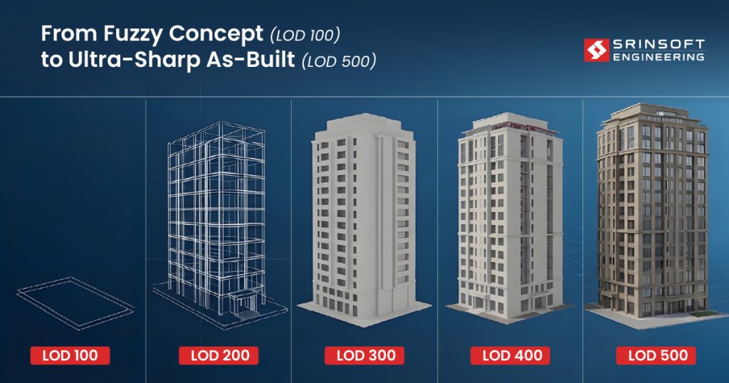
BIM LOD is like image resolution.
Low levels (100) show rough shapes. They are typically used in early conceptual design stages to convey massing and spatial relationships without detailed geometry.
High levels (500) show what actually gets built.
The real problem is teams not agreeing on it upfront.
LOD 300 doesn’t mean the same thing to the architect, the GC, and the MEP contractor. That gap is where coordination breaks and RFIs start stacking.
This guide breaks down each level in real project terms. What’s actually modeled, BIM modeling accuracy levels, what you can trust, and where things typically fall apart.
Why LOD Fails in Practice
Everyone uses BIM LOD 100 to 500. Almost no one actually agrees on what it means.
That should bother us more than it does.
The problem is actually contractual and behavioral. LOD gets declared in the BEP, tied to a milestone, and then essentially forgotten. No one audits it. No one pushes back. The model gets stamped LOD 300 and that stamp takes on a life of its own — quantity surveyors, fabricators, installers — all building on assumptions that nobody stopped to question.
And then reality shows up on site. It’s expensive, it’s disruptive, and someone is about to have a very bad week.
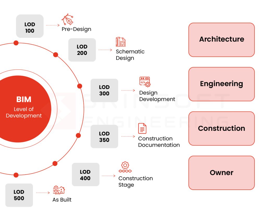
BIM Level of Development
BIM LOD 100 to 500 is a declaration of what an element can be trusted to communicate and who should be acting on it.
| LOD | What it means in practice | Who acts on it |
| 100 | Massing and intent. Approximate geometry, no system assigned | Owner, PM |
| 200 | System identified. Building/elements are shown with approximate shape. Not yet documentable | Design team, early engineering |
| 300 | Assembly documented and coordinatable. Geometry is accurate | All consultants |
| 350 | Interfaces defined. Elements can be coordinated at connections and transitions | GC, trade coordination |
| 400 | Fabrication and installation ready. Shop drawing level | Subs, fabricators |
| 500 | Verified as-installed. As-built model. Reflects field conditions, not design intent | FM, owner handover |
What is LOD in BIM – BIM LOD 100 to 500 explained
LOD 100: Concept Design
Heavily pixelated. You see shapes, not detail.
The model exists to answer one question: does this scheme work at all?
At this stage, the model represents intent, not decisions. You’re working with basic geometry and parameters. Area, height, volume, location, orientation. It’s the sketch before the sketch.
Nothing here is coordination-ready. Nothing should be quantified with any real confidence. The model is showing you floor plates, core locations, rough vertical zones, not locking anything in.
Real-world example
A hospital massing model tested three site orientations against solar exposure, emergency access routing, and floor plate efficiency. No structure, no systems — just enough geometry to eliminate two schemes before detailed design spent money on them.
What goes wrong
An MEP team runs clash detection on the same model and flags shaft conflicts. The shaft is a zone, not a design decision. Every change made in response gets undone at LOD 300. Real coordination effort spent resolving a problem that didn’t exist.
Bottomline
Use it to align direction. Not to validate design.
LOD 200: Schematic Design
Clearer, but deceptive. Forms take shape, but not enough to act on.
This is where things start to get dangerous.
Elements now have approximate size, shape, location, and orientation. You can attach non-geometric data. The model is starting to look like something.
Real-world example
An office building MEP model has duct routes laid out with approximate sizing — enough to validate ceiling zones and floor-to-floor heights across three structural scheme options. A decision gets made. That’s LOD 200 working correctly.
What goes wrong
The procurement team sometimes extracts quantities directly from the LOD 200 model, but at this stage system routes are under coordination and element sizes are approximate. BOQs were revised twice before detailed design closed. The model was doing its job — procurement was using it for something it wasn’t built for.
Bottomline
It’s directional. It’s saying roughly this, roughly here, roughly this big. It is not making promises.
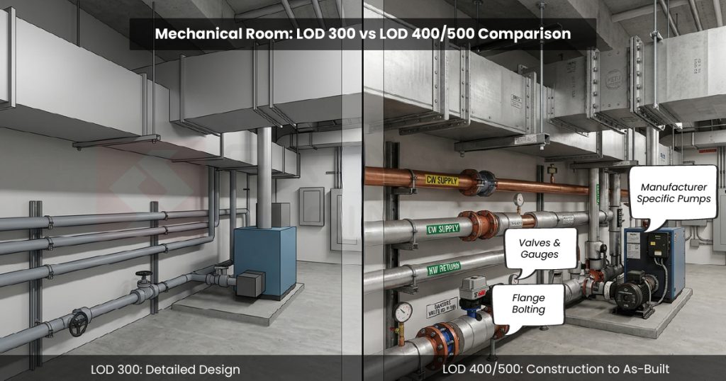
LOD 300: Detailed Design
Clear image. You can recognize and measure what’s there. Still not everything is visible.
Elements are defined. Systems are assigned. Size, shape, location, orientation. Teams across disciplines are pulling from the same model, coordinating against the same geometry.
It “feels” like things are under control.
Real-world example
Commercial fit-out, three disciplines at LOD 300. Beams accurate, duct routes planned against real clearances, clash detection clean. The model is doing its job.
What goes wrong
MEP had modeled primary runs; offsets were assumed. Structural tolerances inconsistently applied. Clash detection still ran clean. On site, ductwork hit a beam. Nobody misrepresented their submission. LOD 300 meant something different to each of them and nobody verified it.
Bottom line
LOD 300 only works if all trades are actually at 300. Before moving on: can this model drive procurement without manual correction? If quantity data needs manual checking before anyone acts on it, the model isn’t at 300 — regardless of what the stamp says.
LOD 350: Construction BIM Standards Documentation
Sharper image. Edges, overlaps, and interactions become visible. Hidden issues start showing up.
LOD 350 — sheets submitted alongside the model.
At LOD 300, things looked fine. Clashes were resolved, coordination signed off, everyone moved on. But LOD 300 was still leaving things out — connections, supports, hangers, access zones. The gaps were always there.
Interfaces get real here. Elements don’t just exist anymore — they connect, interact, and sometimes fight for the same space.
Real-world example
Pipe racks clear clash detection at LOD 300. At 350, supports, hangers, and maintenance clearance zones get added. Conflicts with cable trays appear immediately. Caught here, it’s a coordination fix. Caught on site, it’s a variation order, a delay, and a very uncomfortable conversation.
What goes wrong
LOD 300 sign-off gets treated as the coordination finish line. Procurement moves, fabrication gets scoped, and nobody wants to reopen a package that was supposedly closed.
Signal to watch for: If supports, hangers, and access zones aren’t in the model at 300 sign-off, the coordination isn’t finished — it’s deferred.
Bottom line
LOD 350 exposes the gaps that 300 hides. This is where coordination proves itself. Before sign-off: would a subcontractor trust this for installation? If the answer is anything other than yes, the coordination package isn’t closed.
LOD 400: Fabrication & Assembly
High resolution. Fine details are defined and usable. Ready for execution.
LOD 400 — the model plus shop drawings
This is execution territory.
Every element is a specific assembly. Details are resolved. The model is making commitments. And that shift in purpose changes everything about who should be driving it.
Which is why ownership matters more here than at any other stage.
When the wrong people are authoring LOD 400 content, the model doesn’t just become less useful — it becomes actively harmful. Design teams pushing into fabrication detail without contractor input are making decisions they don’t have the context to make. Constructability, shop constraints, sequencing — these aren’t design considerations. They belong to the people doing the building.
Real-world example
Structural steel connections modeled in detail by the design team. The fabricator picks them up and immediately starts revising — shop constraints, equipment limitations, standard connection preferences. The model and the shop drawings quietly diverge. Site follows the shop drawings. The model becomes decoration.
What goes wrong
The model and shop drawings diverge quietly. No one flags it. Downstream trades keep coordinating against geometry that no longer reflects what’s being fabricated.
Signal to watch for: If the fabricator is making revisions that aren’t being pushed back into the model, the model has already stopped being the source of truth.
Bottom line
LOD 400 must align with who is actually building it. Otherwise the model becomes irrelevant. The question to keep asking: what assumptions are embedded in this model that aren’t documented? Undocumented fabricator decisions sitting inside geometry that’s still being used for coordination are the fastest route to field conflicts nobody can explain.
LOD 500: As-Built
True-to-life image. What you see matches reality.
LOD 500 — the model plus as-built drawings
This is the finish line. What’s in the model should match what’s in the building. Exactly.
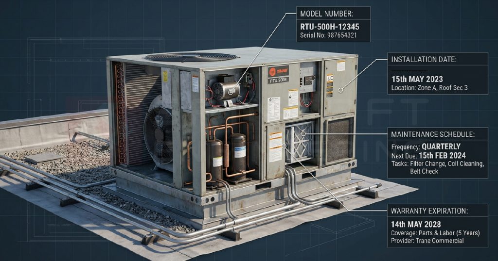
Actual size, shape, location, quantity — plus the data that keeps a building running. LOD 500 is for the people who will operate this building for the next thirty years. It’s a promise that the model reflects reality.
And that promise gets broken more often than anyone admits.
The assumption that a model becomes LOD 500 at handover is one of the most expensive misconceptions in the industry. LOD 500 requires field verification. It requires update workflows. It requires someone, on site, confirming that what was installed matches what was modeled. And that process is unglamorous, easy to deprioritize, and almost always underfunded.
Real-world example: Hospital mechanical room handed over with a verified as-built model. Every piece of installed equipment — actual make, model, location, clearances — captured through a structured site verification process during construction. Two years into operations, the FM team needs to replace a chiller. They pull the model, confirm access routes, identify clashing services, and plan the lift sequence before anyone sets foot in the plant room. No surprises. No lost time.
Remember: LOD 500 is only as good as your site capture and update process. Get that right, and the model stops being a project deliverable and starts being a genuine operational asset — one that earns its keep long after the project team has moved on.
Difference between LOD 100 200 300 400 500 - Mapping LOD to Actual Decisions
The wrong question is what LOD are we at? The right questions are: can we coordinate against this? Can we quantify from it? Can we fabricate off it? Can we install from it?
| LOD | Coordinate | Quantify | Fabricate | Install |
| 100 | ✗ | Gross only | ✗ | ✗ |
| 200 | ✗ | Approximate | ✗ | ✗ |
| 300 | ✓ | ✓ | ✗ | ✗ |
| 350 | ✓ | ✓ | ✗ | ✓ |
| 400 | ✓ | ✓ | ✓ | ✓ |
| 500 | ✓ | ✓ | ✓ | Verified |
Run this against your next model review. If the team can’t answer those four questions, the LOD number has no value.
Practical Framework: How to Actually Manage LOD on a Project
Specify what “mechanical at LOD 300 by DD” means — mains versus branches, equipment to footprint versus connection point, primary framing versus embedments. If it isn’t written down at that level, everyone will interpret it differently and nobody will be wrong.
Align on definitions before the first federated model review. LOD 300 means something different to the architect, the structural engineer, and the GC. Get one agreed definition per element type, on this project, in writing, at kickoff.
And watch for teams modeling beyond their declared LOD. It looks like initiative. It’s actually undeclared assumption — and assumption embedded in geometry is the hardest risk to catch before it costs someone.
Work With a Team That Knows the Difference
The teams that get this right are agreeing on definitions before the first model review, auditing against those definitions at every milestone, and pushing back when a stamp doesn’t match what’s actually in the model.
That discipline is harder than it sounds — and it compounds. A project that manages LOD seriously from 100 through 500 spends less time in RFIs, less time in variation disputes, and less time explaining on site why the model said one thing and reality said another.
Srinsoft delivers LOD 300–500 across architectural, structural, and MEPF — coordination, shop drawings, and as-builts. If you’re working on a project where that rigour matters, talk to the team
FAQs
1. What does LOD actually tell me on a project?
It tells you what decisions you can safely make from the model. Not how detailed it looks.
2. Can I use the model for procurement at LOD 300?
Only if quantities don’t need manual correction. If they do, you’re still carrying risk.
3. Why do teams still get coordination issues even after clash detection?
Because clash detection checks geometry, not constructability. Missing supports, access zones, and tolerances cause the real problems.
4. When is coordination truly “complete”?
Not at LOD 300 sign-off. Only when interfaces, connections, and installation constraints are modeled and validated.
5. Why does LOD fail even when it’s clearly defined in the BEP?
Because no one audits it. The label stays. The model drifts. Decisions get made on unchecked assumptions.